 The mechanical enclosure for the electronics is a simple
combination of plastic, masonite, and hot melt glue.
It should be easy to come up with something at least as
effective.
The mechanical enclosure for the electronics is a simple
combination of plastic, masonite, and hot melt glue.
It should be easy to come up with something at least as
effective.
It is probably best if you can find somebody who is at least semi-skilled in electronics to breadboard this circuit. The information should say what is needed, but if there is any ambiguity, someone adept in electronics should be able to understand the schematic and draw appropriate conclusions.
The mechanical enclosure for the electronics is a simple
combination of plastic, masonite, and hot melt glue.
It should be easy to come up with something at least as
effective.
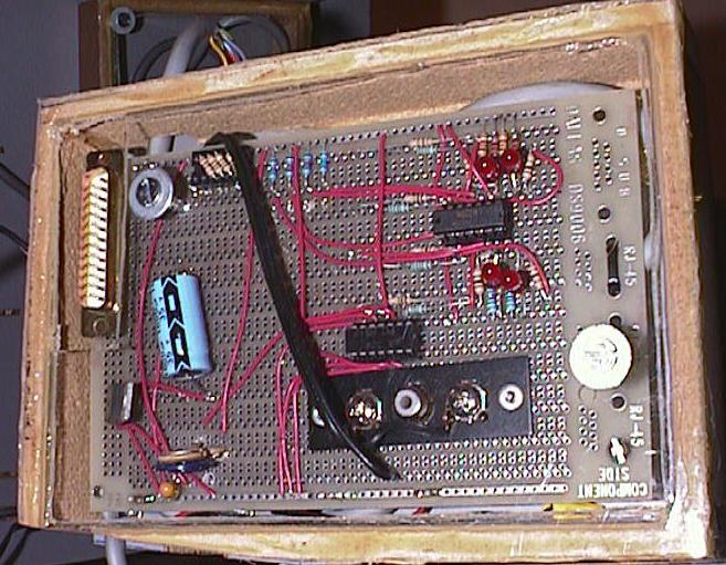
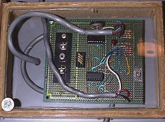
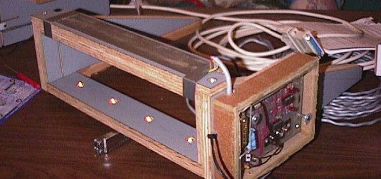
The electronics for the bottom is on the left. It has the DB-25 used to connect the electronics to the parallel port of the computer. The electronics for the top is on the right.
The way that the printer port is implemented on the IBM-PC and compatible allows for a number of signals to travel from the printer to the computer. Printers use these lines to signal such things as out of paper, printer ready and similar things. We use those lines to pass information about the track.
 The design of the the start gate and the exit gate are very
similar. There is a photo sensor per lane, and a very bright
LED to provide input to the photo sensor. To prevent ambient
light from triggering the sensors, the sensors are mounted on
a cross bar above the track, and the LEDs are underneath the
track pointing up at the appropriate sensor. There is a trim
pot to adjust the sensitivity of the sensors. You want them
to detect a car going through, but not be affected by the LEDs
in the ajoining lanes.
The design of the the start gate and the exit gate are very
similar. There is a photo sensor per lane, and a very bright
LED to provide input to the photo sensor. To prevent ambient
light from triggering the sensors, the sensors are mounted on
a cross bar above the track, and the LEDs are underneath the
track pointing up at the appropriate sensor. There is a trim
pot to adjust the sensitivity of the sensors. You want them
to detect a car going through, but not be affected by the LEDs
in the ajoining lanes.
The start gate is connected to the exit gate with a special cable which carries power to the start gate, and the start signal back to the exit gate where it will be put to a connector so that the computer sees it. The unused inputs of the op-amps must be commited. For the LM339, pin 3 should be tied to +5V, and pin 12 to ground. For the LM324, pins 4, 5, 12, 10 are tied to +5V, and pins 11, 6, 13, and 9 are tied to ground.
The phototransistors are simple parts. We got them as Digikey L14R1QT-ND. The LEDs shown in the schematic are for diagnostics. Adjust the trim pot until all of the LEDs are on, then turn it the other way until just after all of the LEDs go dark. You can then test the sensitivity of the circuit by putting a car (or your finger) in the light beam, and the corresponding LED should turn on.
The main illumination LEDs are bright. We received some sample parts from HP and they work great. Digikey as some 1500 millicandle superbright LEDs as part number LT1104-ND. These are connected to +5V through a 125 to 300 ohm resistor to ground. The resistor value should be an appropriate size to get sufficient brightness and not burn out the LED.
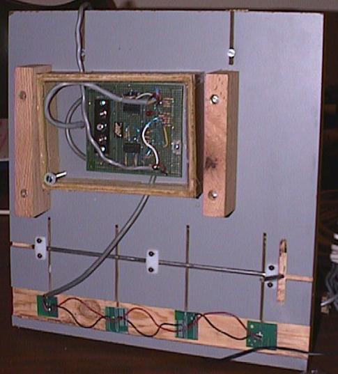
The exit gate has the sensor from each lane going to the computer.
The schematic for the start gate is similar to the bottom one, except that the outputs of the four sensors are combined together to form a single start signal. This can be done with a simple TTL part or building something up with diodes or transistors. Yes, this is a bit sketchy. An alternate way of doing the start gate is to put a switch on the starting lever, or to use a single lane as the starting lane and use just a single channel of the optical sensors for that lane.
The parallel port input for an IBM-PC does some interesting things to the signal. Lanes 1, 2, and 3 are inverted signals, but lane 4 is not. This little detail is handled in software. The voltage level at the electronics package has the output in a high state when no car is present, and in a low state when the sensor is in shadow.
Power is supplied by a 9V transformer which plugs into a 110V
outlet. This power is converted to 5V by a three terminal
regulator for use in the electronics at the finish gate,
and is also sent to the electronics at the starting gate.
We built the circuit on a piece of perf board. Parts placement should not be critical, however the connector for the cable to the computer should not stick out into the walk area, but should be parallel to the track.
The pinout of the DB-25 for the parallel port is as follows:
The electronics are mounted in small boxes attached to an assembly which is stored more carefully than the track proper.
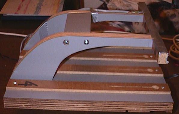
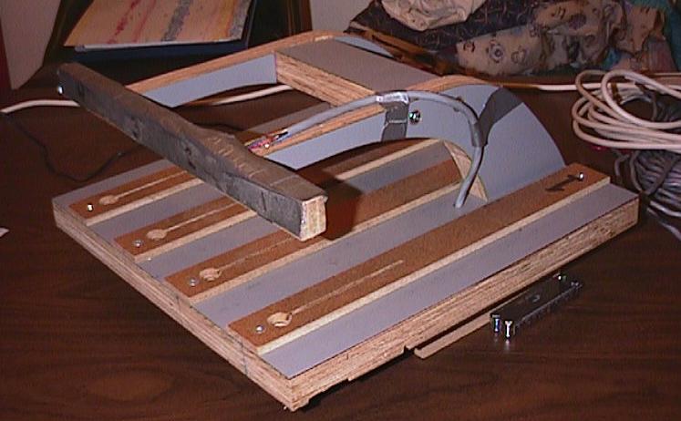
 The bottom gate occupies just a short distance of track surface
at the bottom of the track. There are guides to align it with
the bottom segment of the track. This part nests nicely with
the starting gate for easy storage.
The bottom gate occupies just a short distance of track surface
at the bottom of the track. There are guides to align it with
the bottom segment of the track. This part nests nicely with
the starting gate for easy storage.
 The starting gate has a starting lever built in.
In our version we have some very tight clearences next to the
rear wheels.
In addition, it is easy to false trigger the start sensor.
Both of these can be worked around, but you may want a slightly
different mechanical arrangement.
For work of this sort, I like duct tape as a construction material.
The starting gate has a starting lever built in.
In our version we have some very tight clearences next to the
rear wheels.
In addition, it is easy to false trigger the start sensor.
Both of these can be worked around, but you may want a slightly
different mechanical arrangement.
For work of this sort, I like duct tape as a construction material.
Last modified 27 May 2006